Field Robot Event 2022 Proceedings
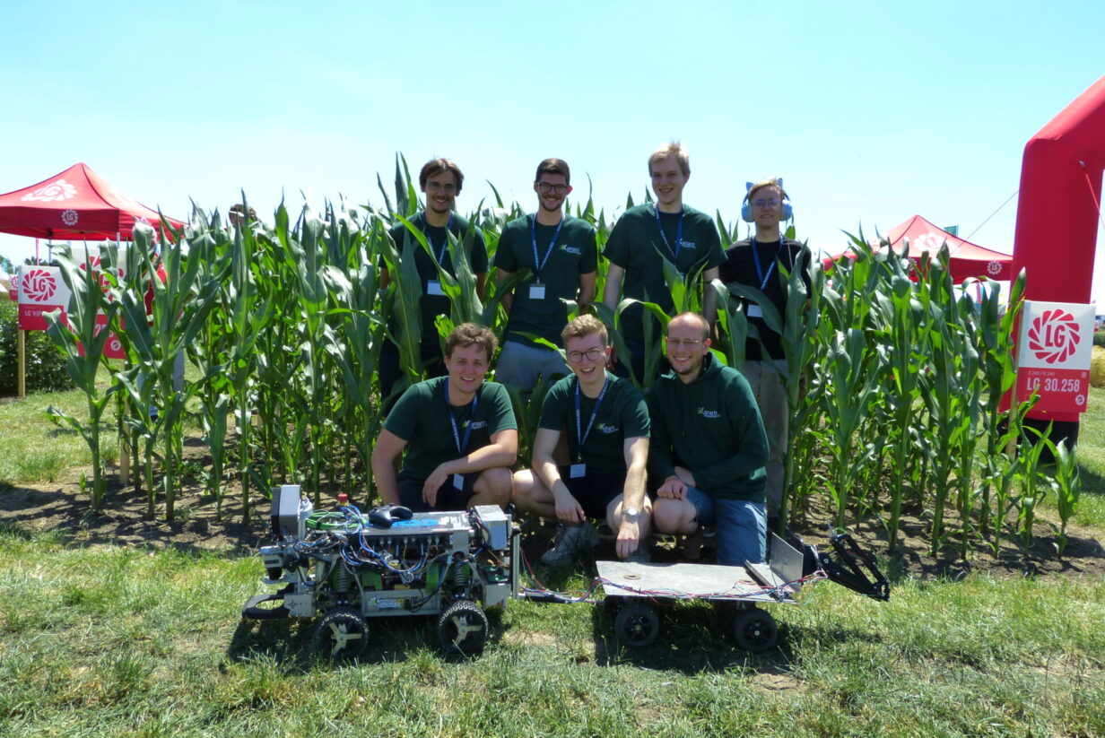
From June 13th to 16th we partook in the annual Field Robot Event, the international field robotics showdown. This year the contest was split in a real world field contest and a virtual field contest which again took place in our virtual maize field simulation environment.
1. Introduction
Kamaro Engineering e.V. is a nonprofit organization and university group at Karlsruhe Institute of Technology. Since 2009 we build autonomous robots for various competitions and regularly participate at the Field Robot Event. We again enjoyed helping to create the competition environment for this year’s simulation part of the event. We updated some small parts of the virtual maize field generator to be able to control the difficulty of each generated row individually. Unfortunately, because of the simulation constraints to ROS Noetic we decided to stick to this ROS version. For us this was also the main reason to use the Jackal model in the simulation part for another time. We felt it did not make sense to create a custom robot description when we update soon anyway. Nevertheless, we were excited for this year’s event because we all wanted to participate in an infield competition again and meet all the other teams in person.
1.1 Our robot — Betelgeuse
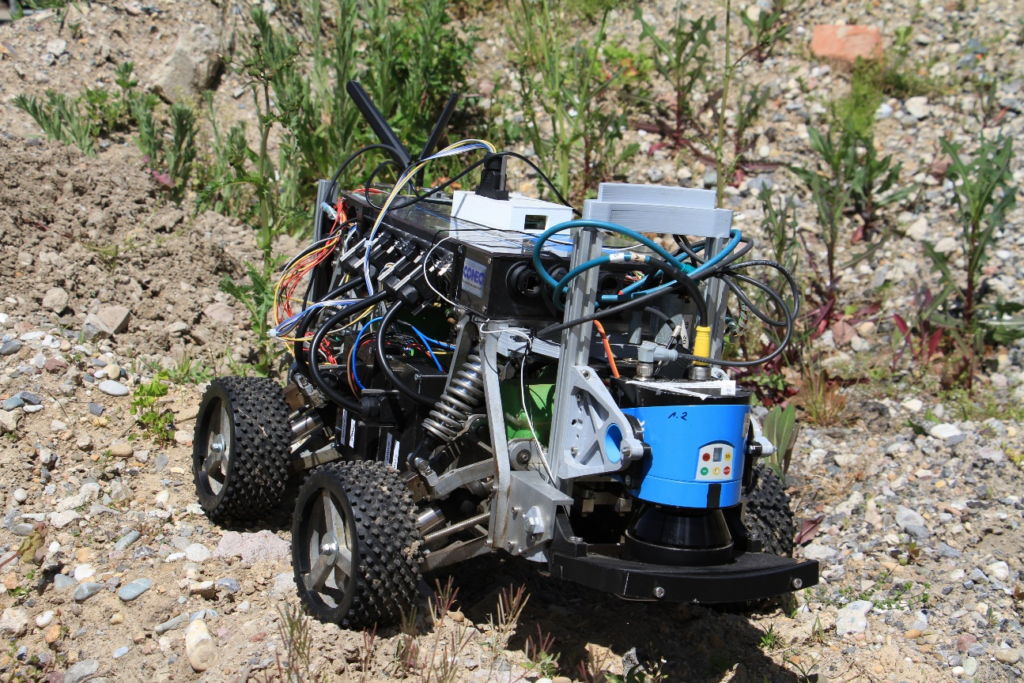
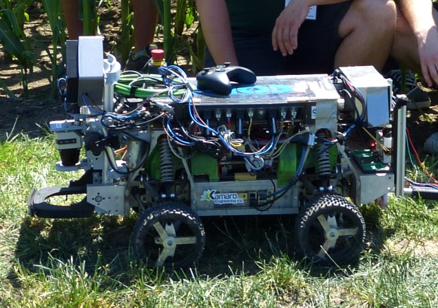
The biggest challenge for us was the decision to use our main robot “Betelgeuse” again. Over the last year, we redesigned this robot from the ground up, by removing most of the electrical components, from sensors and custom circuit boards to all wires. The only parts that we kept untouched were the main frame and the powertrain including the main actuators — i.e., the main motor and the steering motors with their absolute encoders.
With this redesign we tackled two issues: Modularity and Reusability. The old design had one complex primary board that controlled everything. This included communication from and to sensors and actuators as well as to the main computer, some controllers for speed and steering as well as all the code for each custom component that we have developed over the years, such as the sprayer. Therefore, a substantial number of wires across the robot was needed. Maintaining this robot with an ever-changing team got harder and harder. So, we decided that we want full modularity and encapsulation for all components.
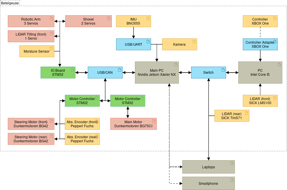
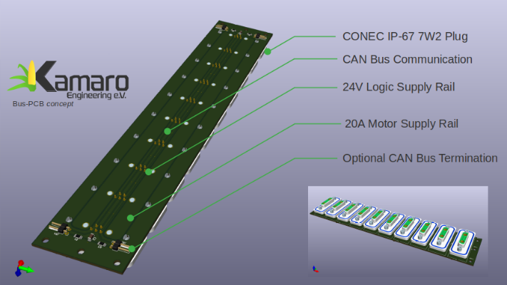
The new concept provides a single cable connection to the new main bus for each module. The new main bus consists of two lines for direct battery power, two lines for the power supply of logic components and two lines for the main CAN bus. With this main bus and the concept constraint we hope to achieve full modularity for our modules. Meaning we should be able to add and remove modules at runtime or even switch modules with a robot using a similar system.
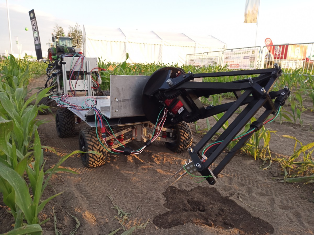
As you can see from the pictures, we could not fully archive our goal yet. The main reason being the current chip shortage causing exceptionally long delivery times for STM32 and other semiconductor components. In the future, we would like to separate the controller of the robot arm with the moisture sensor, the shovel, and the servos for the lidar tilting into their own controllers. Another ongoing project is to integrate the motor controllers for the steering motors into our own controller design.

RODOS
RODOS [1] is a real-time capable and open-source middleware developed by the University of Wuerzburg. The software is especially designed for autonomous systems demanding high reliability. So, besides field robots it is designed to be deployed on drones, submarines, satellites, etc. It provides a real-time capable scheduler for reliably maintaining clock rates. A hardware abstraction layer (HAL) offers easy access to hardware peripherals, like PWM, ADC, CAN, etc. This middleware, like ROS, also enables a publish-subscribe based communication for different hardware and software components over a chosen interface (CAN in our case).
We made the integration of RODOS even easier, by developing a ROS-package called “rodos_gateway” which translates chosen topics from RODOS to ROS and vice versa. To keep this package as maintainable as possible, we decided to not create our own serializer for messages, because this is already done by the package “rosserial”. We use the message headers generated from “rosserial” to generate the conversion code automatically with a self-developed code generator in Rust we integrated into the cmake/catkin build script. After the conversion, the message is published on the other side — either to ROS or on our main CAN bus.
2. Task 1 – Navigation
Task navigation is basically task 1 and 2 from the previous Field Robot Events combined. That means the robot does not only have to traverse straight maize rows on after another for the first task. This new task requires full maize row navigation capabilities, meaning curved rows and headland navigation as well as gaps in the planted rows.
2.1 Row Navigation
Last year, we published our row navigation algorithm that we used for several years. [2] We won task navigation with that algorithm on the virtual Field Robot Event 2021, but we saw that this approach has problems with row gaps that could not be solved in a straightforward way. This was confirmed with our task 2 performance on the 2021 event.
For this year we implemented a particle filter-based algorithm published by Hiremath et al. (2013) [3] for row navigation. The orientation and distance of the two adjacent crop rows are locally approximated using a model of two parallel lines. The model then assumes a higher vegetation density in a small, fixed sized region around the lines. The higher density results in a higher chance that a LiDAR ray is reflected in those regions.
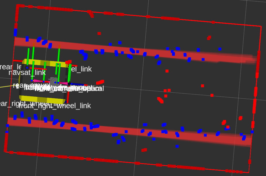
Visualization of the running algorithm. The slightly faded thick red bars are an overlay of the estimated crop row positions of the 30 models with the highest score. The blue dots are LiDAR measurements inside the high-density region, the red dots are measurement outside those regions. Measurements outside the red box are mapped to the border, so only the local region is considered.
By then calculating the probability of the measured distance for each ray of the LiDAR based on those densities, a total probability of a given model can be calculated. These probability models are then used in a particle filter to estimate the robot’s position relative to the crop rows. The resulting orientation and distance of the crop rows is then quite directly used as steering input for the robot.
With some extensions regarding behavior when entering and exiting the row, this algorithm performed well in the simulation despite not having spent a lot of time testing and tweaking it. We were also surprised how well it performed on the real field with a different robot, with only very minor tweaks. However, more tests are necessary here, as we did not get a lot of running time on the real robot this year, due to other components failing or not being ready in time.
The new algorithm also still struggles a bit with big holes in the rows, and the parallel line model means that very curvy rows also lead occasionally to problems. But we see our current implementation as a good starting point for further improvements addressing these issues.
2.2 Row Turning
To detect the end of the row, we count the number of LiDAR points in a wide box in front of the robot. If the number is below a certain threshold for a long enough time, the robot recognizes this as the end of the row and the turn node takes control via the state machine.
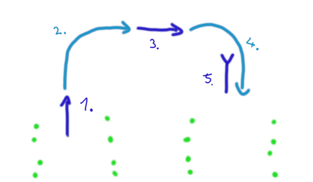
The row change is divided into five substates as shown in the picture above:
- move out: To get a safe distance from the crops, drive a bit forward.
- turn out: Perform a 90 ° turn into the desired direction.
- move along: Drive in parallel to the field’s edge for a distance depending on the number of rows and the average row width.
- turn in: Perform a 90 ° turn in the same direction to face the field again.
- move in: Aim for a certain distance perpendicular to the field edge compared to the starting point of the turn. This is required so that when the row navigation node takes control, the robot is already inside the row and the plants on either side are clearly visible.
During all substates (except turn out/in), the robot compares its expected position with the position given by odometry relative to the turn’s origin point. Any lateral differences are automatically corrected.
The expected row positions directly next to the robot are also compared with the laser scan during the move along substate which is used to correct the route accordingly. However, only for long turns (number of rows greater than 4) do these corrections have any considerable effect, the odometry is good enough in most cases.
While this algorithm can perform well, it always requires extensive parameter tweaking depending on the robot and the soil, and of course a good odometry. For next year we plan to use the particle filter approach used for row navigation also for row turning and headland navigation.
2.3 Simulation
The biggest problem for us was creating the competition container, because we only had limited internet from our phones at the event. In the end, one of our team members who drove back to Karlsruhe overnight, built the container and brought his desktop computer to build the container for task 2.
For the simulation we used the provided default robot (Jackal) as mentioned in the introduction. We were reasonably happy with our performance and managed to get third place. The new row navigation algorithm performed quite well, however row turning left something to be desired. We damaged quite a few plants on row entry due to a misaligned turn, and finally had to abort the run due to turning into the wrong row entirely.
2.4 Field contest
The real environment is always a challenge for the mechanical system, electronics and the software running on the robot. Many times, the main robot frame is well tested and known for all three engineering fields, but still new additions to the robot pose challenges for every team.
For this year, our biggest challenges were the electronics and code for the robot. With the newly built electronics based on RODOS getting the robot “field-ready” took a lot of time. Also, new electronics were required to control new modules for tasks 2 and 3. Engineering them mechanically and electrically also took a lot of effort. Unfortunately, we needed more time than expected and we had little time for testing the code on the robot.
This also meant that we could not test our new row navigation algorithm on the robot in a real environment. So, it was unfortunate but not surprising for us, that something went wrong, and the robot did not start at the infield competition. The first infield tests were done on the testing area of this year’s contest only a couple of minutes earlier.
3. Task 2 – Detection and Mapping – Object Removal
Task detection and mapping resembles task 3 and 4 from the previous Field Robot Events combined. Unlike task navigation this task always had more variety. One of the few things that is always required is object detection of some kind. For this purpose, we always use the camera attached to our robot.
We used a coarse semantic segmentation model with an EfficientNetV2 [4] backbone for object detection of both dandelions and cans. The net was trained on our own hand labeled dataset with over one thousand images that we created together with team Carbonite.
One thing to note here, we did not do the mapping part, in which we could gain additional points by accurately mapping the detected objects. Our two main reasons for this are time and scoring. While the first one is obvious the second is not, but for this we must understand how the scoring works. After the run you hand over the generated table with all the object positions for which you will get points depending on the distance to the true position of the object. That means your reference frames must be equal or you would have a constant offset. You will only get points if the error is smaller than 37.5 cm, if it is bigger you will get –5 points. With this system, the alignment of your local frame of reference with the global frame of reference is crucial. If this does not work; there will be a lot of minus points just for attempting mapping.
3.1 Collaboration with Team Carbonite
Last year, we published our dataset and models [5] for image recognition during the online Field Robot Event 2021. Our blog post [6] ended with a call for cooperation in creating a dataset and AI (Artificial Intelligence) models for this year’s event. Team Carbonite from the Überlingen Students‘ Research Center (SFZ Überlingen) approached and we subsequently worked together on building a realistic image dataset. As a nod to the two team names, this dataset shall henceforth be known by the name “Carbonaro”.
In line with this year’s detection task, the dataset contains coarse semantic segmentation labels for (artificial) dandelion flowers and beverage cans. Each task of FRE 2022 was held both on the real field and in a simulation. Therefore, we publish raw data and trained models for both environments.
Like last year, we are again publishing the dataset [7], trained models, and supplementary materials to aid other teams in the transition to deep learning based, data driven perception methods. Much of the agricultural machinery industry is already shifting to advanced camera-based perception methods. We strongly believe that supporting this development at FRE is necessary to keep the event relevant and attractive in the future. We therefore again invite all other teams to cooperate and pool resources for next year’s dataset.
Have fun exploring the available materials, and please drop us an e-mail if you are interested in joining the deep learning hype train and contributing to the FRE 2023 dataset!
- Publication from Carbonite:
https://github.com/Team-Carbonite/fre2022_ai - Publication from Kamaro:
https://github.com/Kamaro-Engineering/fre22_object_detection
3.2 Simulation
The simulation part worked quite well, despite us training the model on the competition day until 3 am and building the container at 4 am without much testing. We only had a couple of test runs where we decided that “it looked good”. We had 0 false positives and 6 true positives with one damaged plant which got us second place for this task. We had the same detection results as place one — FloriBot, but they managed this task without any plant damage.
3.3 Field contest
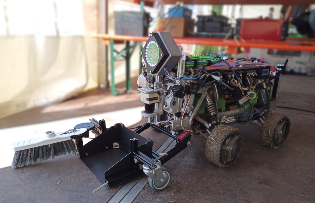
Our concept for task 2 was to detect objects with a webcam and a neural network based on image recognition that we trained as described above. We decided on an active removal for which we constructed a shovel because in the previous rules it was only possible to get points for an actual picking-up-action.
During the design process there are a few points which usually must be considered to make the new structure work within the tight time limits. It must be simple and be constructed and manufactured within a short time frame. Also, it should use as few actuators as possible to reduce errors and workload for all three sub teams, mechanics, electronics, and computer science.
To build the frame of the shovel we took some aluminum profiles because they are very multifunctional and adding parts to it with a screw is quite easy. The shovel itself is built of a hard foam sheet which is stable enough to hold the cans but also slightly flexible. To get the cans on the shovel we took a part of a broom and mounted it to the shovel so that a servomotor can open and close it. A second servomotor can tilt the shovel for the picking-up-action. Some wheels keep it at the right distance from the ground. The construction is quite complex, and we did not have a lot of time to test it.
The servomotors are an easy to use and compact solution. For their control, a new electronics circuit with 5 V power and PWM-signals was built. To step down the battery voltage we chose an LM2596 from Texas Instruments as power electronics. It is an integrated step-down converter with an output current capability of 3 A. The generation of the PWM-signals and the communication interface were realized with an STM32 running RODOS.
Our approach to the problem of removing cans worked well, as there was only a small workload for our busiest sub team computer science during and before the competition regarding this. Unfortunately, the lack of testing on the real field made us overlook some problematic scenarios, which led to a critical failure after we successfully picked up the first can.
Our approach for detecting dandelions sadly did not work in the field. We think the main reason was our fisheye camera where we — due to a lack of time — did not restrict the detection area and therefore probably detected dandelions all over the field. But one counter point to this hypothesis is that the can detection worked well enough to pick up the first can. We are not 100% sure what went wrong there.
4. Task 3 – Freestyle
Keeping the soil hydrated is one of the most important parts when growing maize. We experienced this on our own test-field where some plants grew well whilst others were hardly distinguishable from weeds around them. Thus, our mechanics team decided to build a robot arm from soil moisture measurement.
First, we looked at previous robot arm projects from several years ago which were cancelled because they did not work. One of the biggest problems was the weight of the arm. That is why we decided to construct the arm in a lightweight design and use our 3D-Printer to print it with PLA. We realized the joints by using some aluminum pipes which do not have much friction in combination with our printed parts. A parallel cinematic makes sense because the sensor needs to be always at the same angle while measuring. The bearing for the rotation of the entire arm is a furniture bearing from the hardware store because it can easily handle the weight of the arm.
For the movement of the arm-joints we went again with servomotors. Since servo motors were also used for the shovel in Task 2 the controlling PCB was deployed again. With RODOS the communication interface for the arm stayed the same. The STM32’s ADC converted the analog signal of the soil moisture sensor and published its value on a new topic. Thus, providing it to the software running on the PC.
To control arm movements, a simple keyframe system with linear interpolation was used. The controlling program runs on the Nvidia Xavier NX, as a node in the ROS framework. Such a system was necessary because the servos themselves would move to any target angle at maximum velocity. When interpolating between two keyframes (each containing 3 angles for the 3 servomotors), the maximum of the three angle differences multiplied by a constant would determine how long the program would wait before steering to the next keyframe. This in effect creates asynchronous Point-to-Point (PTP) interpolation. At startup, the robot arm (with a very sharp measuring instrument) would snap to a neutral position, which is a safety hazard that for now cannot be effectively mitigated, because our robot arm does not have any sensors to read the current joint angle. This position is also the first keyframe position. To measure the ground moisture level, the robot arm will drive the measuring rods into the ground and hold that position for a custom time that is sent to the arm controller via RODOS. After that it will play the keyframes backwards, eliminating the work of creating a return path. The last keyframe then is also the starting keyframe, creating a loop able motion.
5. Comparison Simulation versus Field
Simulation proved to be an important part in developing and verifying new algorithms. While the real robots’ mechanics and electronics were not ready for field tests up until the actual event, the simulation allowed us to do quick iterations when developing new software.
Of course, we do not have one-to-one parity of our simulation and field code since we used the standard Jackal model with drastically different kinematics compared to Betelgeuse. However, especially the new row navigation algorithm, which was only developed and tested in the simulation, worked surprisingly well on the real robot with only minor tweaks. On the other hand, row turning required two very different configurations for simulation and field.
Object detection with our neuronal network in the simulation proofed not to be very comparable to the real world. While our detection worked very well in the simulation, it produced a lot of false positives in the real field. Because we did not have any time to test it on the field, we do not know if this could have been fixed with only minor tweaking. However, there is also a good chance that the neural network was overfitted to the comparatively plain lightning conditions in the simulation.
As we had multiple unfortunate incidents like one of our LiDAR’s dying, we were delighted to still compete with our competitive software in the simulation and win prizes despite the unfortunate circumstances in the field. With Betelgeuse now being field-ready we look forward to competing in next year’s FRE.
6. Conclusion
Overall, we are very satisfied with our performance at this year’s event. We started with an untested robot and a lot of untested hardware modules and in the end had a working code for all of them. We even managed to win some prizes in the simulation parts and got the third prize in overall simulation. We had a lot of fun at the event by meeting the other teams, running untested working code, and attending DLG.
Additionally, we are happy with the collaboration with team Carbonite and hope more teams will join in the future. Object detection with image recognition is a crucial part of any real robot application, especially when working in agriculture. Using semi realistic weed models was also a good first step and we hope this trend — to more realistic applications — will continue in the future.
7. References
[1] https://gitlab.com/rodos/rodos/ (2022-08-01)
[2] https://kamaro-engineering.de/?p=1729 (2022-08-01)
[3] Hiremath, Santosh A., et al. „Laser range finder model for autonomous navigation of a robot in a maize field using a particle filter.“ Computers and Electronics in Agriculture 100 (2014): 41-50.
[4] Tan, Mingxing, and Quoc Le. „Efficientnetv2: Smaller models and faster training.“ International Conference on Machine Learning. PMLR, 2021.
[5] https://github.com/Kamaro-Engineering/fre22_object_detection (2022-08-01)
[6] https://kamaro-engineering.de/?p=1709 (2022-08-01)
[7] https://kamaro-engineering.de/?p=1838 (2022-08-01)
8. Sponsors